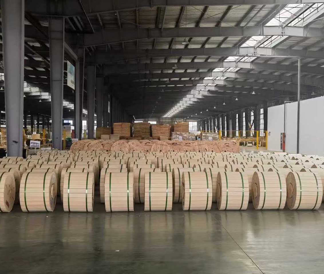
 Optical Fiber
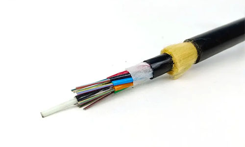 ADSS Fiber Optic Cable
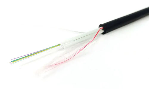 ASU Fiber Optic Cable
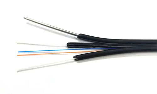 FTTH Fiber Optic Cable
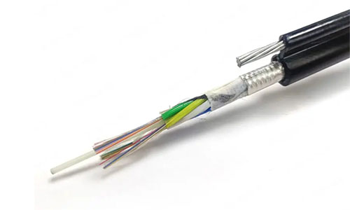 Figure 8 Fiber Optic Cable
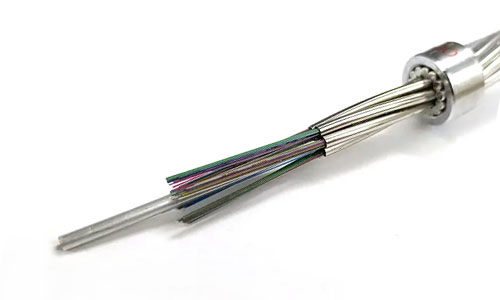 OPGW Fiber Optic Cable
 Coaxial Cable
 Ethernet Cable
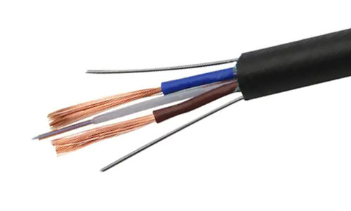 Photoelectric Composite Fiber Optic Cable
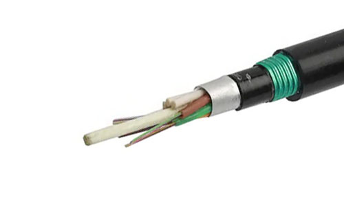 Underground & Pipeline Fiber Optic Cable
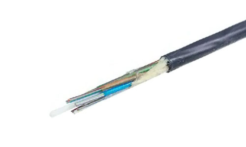 Air-Blown Micro Fiber Optic Cable
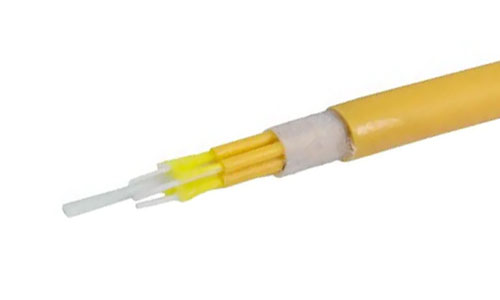 Indoor Fiber Optic Cable
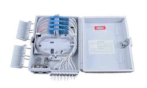 Fiber Optic Distribution Box
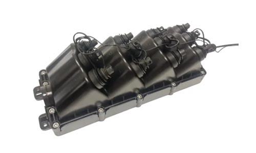 Multiport Service Termina Box
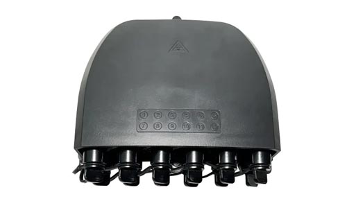 Fiber Optical Terminal Box
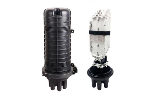 Fiber Optic Splice Closure
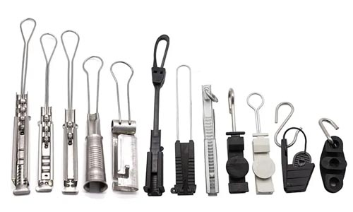 Fiber Optic Clamps
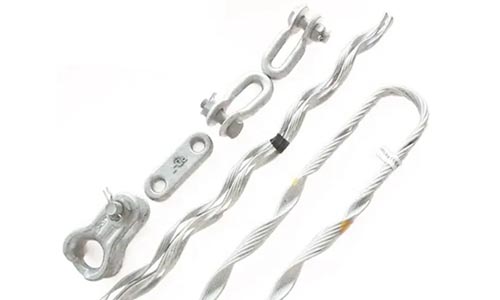 Fiber Optic Cable Fittings
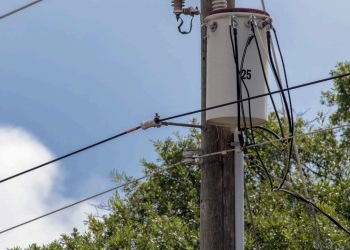 ADSS Fiber Cable
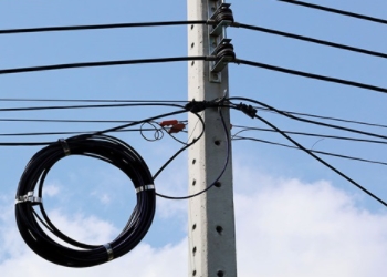 ASU Fiber Cable
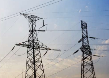 OPGW Fiber Cable
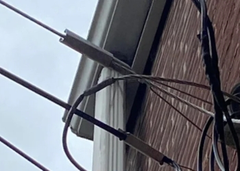 FTTH Fiber Cable
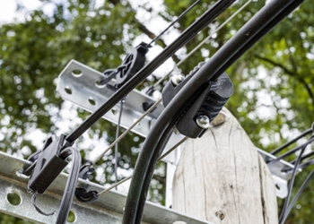 Figure 8 Fiber Cable
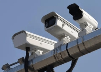 Photoelectric Composite Fiber Cable
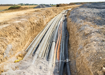 Underground & Pipeline Fiber Cable
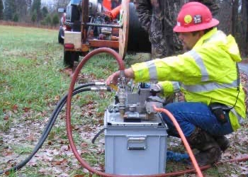 Air-Blown Micro Fiber Cable
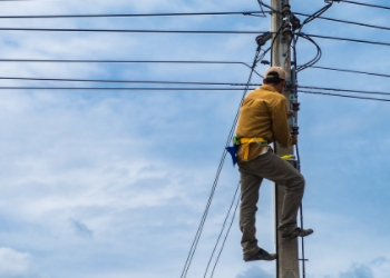 Aerial Fiber Cable
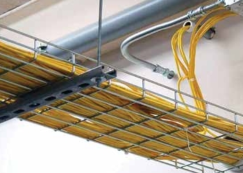 Indoor Fiber Cable
 Fiber Optical Terminal Box
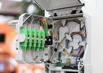 Fiber Optic Distribution Box
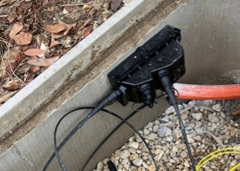 Multiport Service Termina Box
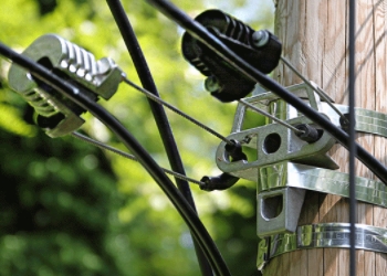 Fiber Optic Clamps
 About Us
 Our Team
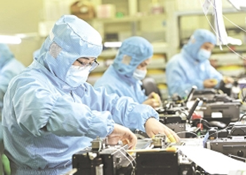 History
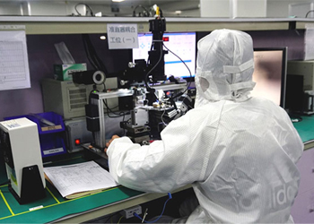 R&D Strength
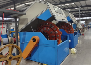 Production Base
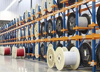 Warehouse & Logistics
 Quality
 FAQs
FAQsIntroduction to Fiber Bending Loss
Contact us for more sample, According to your needs, customize for you.
inquiry nowIntroduction to Fiber Bending Loss
Fiber bending loss refers to the loss of signal that occurs when an optical fiber is bent beyond a certain radius. This phenomenon is due to the leakage of light from the core of the fiber as it travels through the cladding. When a fiber is bent, the light rays undergo total internal reflection at the core-cladding interface. However, if the bending radius is too small, some of the light rays may escape through the cladding, resulting in loss.

The fiber bending loss depends on several factors:
Bending Radius: The smaller the bending radius, the higher the bending loss. This is because a smaller bending radius causes the light rays to experience greater curvature, increasing the likelihood of leakage through the cladding.
Fiber Type: Different types of fibers have different bending loss characteristics. For example, single-mode fibers typically have lower bending losses compared to multimode fibers.
Wavelength: Bending loss can vary with the wavelength of light transmitted through the fiber. Some wavelengths may experience higher bending loss than others.
Fiber Design: The design of the fiber, including the refractive index profile and the materials used, can influence bending loss.
Coating: The type and quality of the coating applied to the fiber can affect its flexibility and resistance to bending loss.
To minimize bending loss, it's important to handle optical fibers carefully and avoid excessive bending, especially sharp bends. Fiber optic cables are often designed with protective layers and reinforcements to mitigate bending loss and ensure reliable transmission of signals.

In the application of optical fiber, a more complex type of optical loss is micro-bending loss. With the development of devices and optical fibers, micro-bending loss is a more concerned loss factor. More direct optical switching is introduced in the device instead of electrical switching, and the fiber is susceptible to long-term stress in a very small space. For the fiber, the thinner fiber, the smaller diameter fiber, either by reducing the thickness of the coating, or by reducing the diameter of the cladding; Similarly for multi-core fibers, the effective cladding thickness will also be greatly reduced, which increases the risk of micro-bending loss.
Micro-bending loss and macro-bending loss are related to bending literally, but there are obvious differences between them from the point of view of the mechanism of loss occurrence. Therefore, in practical applications, it is very necessary to distinguish the loss from micro bend or macro bend according to the nature of the loss, which involves the correct location of the problem and the way to solve the problem.
1. In terms of geometric deformation
The micro-bending loss is actually a loss introduced by the slight deformation of the fiber, while the macro-bending loss is the loss introduced by the real bending, and the outer diameter of the fiber remains the ideal constant. This makes a clear difference in geometry. The small deformation of the fiber can be treated as the high-frequency perturbation of the geometric circumference in the longitudinal direction of the fiber. This perturbation has two attributes: amplitude and frequency. The scene of micro-bend comes from high frequency and low amplitude. The external disturbance can be simulated, and its frequency and amplitude change randomly with time. Taking the Fourier transform of this random variation, the magnitude is equivalent to the power, and there is a corresponding correspondence between the power spectral density and the spatial frequency

This is also intuitively easy to understand and draw a qualitative conclusion: when the disturbance frequency is very high, the deformation of the fiber is uniform, and the influence of micro-bending loss is not large. However, when the disturbance frequency is very low, the real bending may form, and the macro-bending loss is dominant.
2. From the loss mechanism
In the macro-bending loss, it can be considered that the mode field distribution of the fundamental mode (single-mode fiber) in the fiber diffuses to the bending side, and the part that diffuses deep into the cladding will form radiation and gradually lose. In the micro-bending loss, part of the power of the fundamental mode propagating in the ideal fiber is coupled to various higher-order modes under the condition of perturbation. As the propagation distance increases, the power carried by these higher-order modes is radiated out of the Oran ten-element fiber, and of course it may be re-coupled back to the fundamental mode

The analysis of micro-bending loss is typically based on mode coupling theory, and the basic relationship is a bit complicated.

Where C is the coupling coefficient between the fundamental mode and one of the higher-order modes, which indicates how much power will be coupled from the guided mode to the higher-order mode or cladding mode (single-mode scenario). Qfiber is the disturbance of the fiber under direct stress, and Qenv is the disturbance under indirect stress when the environment changes. The accuracy of this modeling analysis is difficult because the perturbations that cause the micro-bending losses are highly random, but the purpose of the analysis is to provide a strong guide, and in certain scenarios, additional coefficients can be used to approximate the simulation results.
olshansky studied and proposed an observational relation in the early stage.

a -Core radius
b - Cladding radius
Delta - refractive index difference
Elastic modulus of the EE-polymer coating
Eg -Elastic modulus of optical fiber glass
For most use cases, this relationship is more helpful
3. Source of micro-bending loss
The source of micro-bending loss is mainly external factors. If the fiber is only used as a bare fiber without cable forming, if there is no external force in the free space, there is no possibility of micro-bending loss. Although the geometric irregularity of the fiber itself may have the possibility of micro-bending loss, the influence of micro-bending loss of the fiber itself can be ignored because the loss test has been passed in the factory test. It only considers the influence of micro-bending loss of optical fiber corresponding to external fixation in optical cable or device.
The sources of micro-bending loss mainly come from three aspects
The first is the design of the fiber itself. The design of the fiber itself is not the source of micro-bending loss, but the sensitivity to micro-bending is determined by the fiber design itself. The design of the fiber core is mainly influenced by the MAC value. This is consistent with Olshansky's feature formula.

The smaller the MAC is, the smaller the micro-bending loss will be under the same external perturbation.

This is reflected in the specific fiber, generally G657 fiber has less micro-bending loss than G652 fiber ·

Although reducing the core radius and increasing the refractive index difference can reduce the micro-bending loss, the correlation between the fiber parameters and the standardization of the fiber are unlikely to exist in the scenario of only changing one parameter while the others are unchanged. But the trend continues.

The design of the cladding in the fiber can also bring improvements. The wavelength dependence of the microbending loss varies greatly when a specific groove design is added to the cladding.
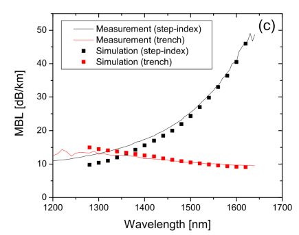
The wavelength dependence of the microbending loss of the grooved fiber in the figure is very different from that of the standard fiber. The wavelength dependence of the standard fiber in this figure is slightly beyond the conventional data, mainly for the grooved design fiber whose micro-bending loss is flattened. This means that the usual problem location and problem analysis needs to consider the design of the fiber, otherwise just based on experience can be misleading. In summary, the design of the fiber optimizes the micro-bending loss, which is beneficial for certain scenarios
Secondly, the source of micro-bending loss is related to the factor of optical fiber cable, which is more complex. The complexity lies in the fact that there are too many types of optical fiber cable and the design is very different, but it is relatively easy to be specific to a certain type. A typical factor is the influence of coating. Intuitively, it can also be concluded that the coating, as the first line of defense to protect the fiber, plays the role of effective stress conduction. If the coating is used as a stress transfer function, the smaller the internal elastic modulus is and the larger the external elastic modulus is, the smaller the value of the stress transfer function is, and the influence of the corresponding micro-bending loss is also smaller. The larger the diameter of the coating is, the smaller the influence of the micro-bending loss is consciously known.

Obviously, the diameter of 900um is much smaller than the microbending loss of 250um fiber. It can also be known that in the same design of fiber optic cable, although the activity space of 900um fiber is small, under normal circumstances, its micro-bending loss is indeed much smaller in the cable
The third factor is the impact of the environment in which the cable is located. Due to the complexity of micro-bending loss, there is no standardized test method at present, and the test method provided by IEC/TR62221 is generally used directly. It is difficult to determine the perturbation. Even for certain test methods, test environments and test equipment, different placement locations may have different results. The results of different laboratories and different test methods cannot be directly compared, but are all qualitative comparisons. For its test results, it needs to be evaluated separately.