 Optical Fiber
 ADSS Fiber Optic Cable
 ASU Fiber Optic Cable
 FTTH Fiber Optic Cable
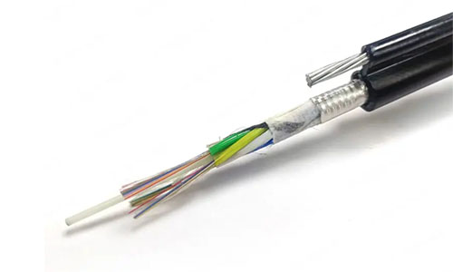 Figure 8 Fiber Optic Cable
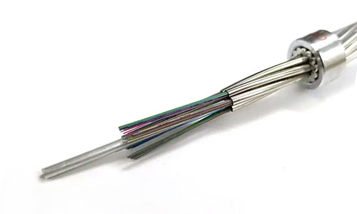 OPGW Fiber Optic Cable
 Coaxial Cable
 Ethernet Cable
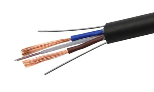 Photoelectric Composite Fiber Optic Cable
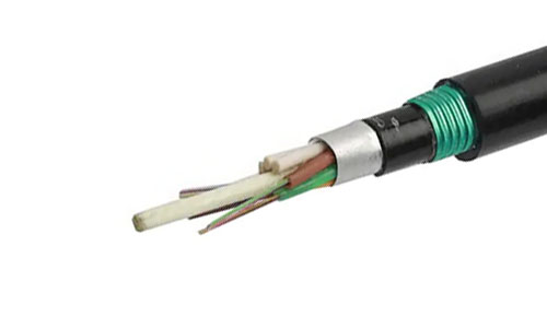 Underground & Pipeline Fiber Optic Cable
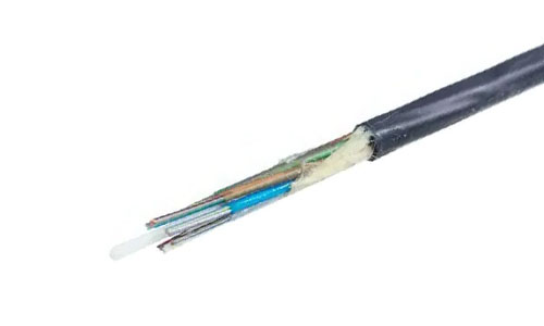 Air-Blown Micro Fiber Optic Cable
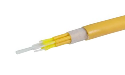 Indoor Fiber Optic Cable
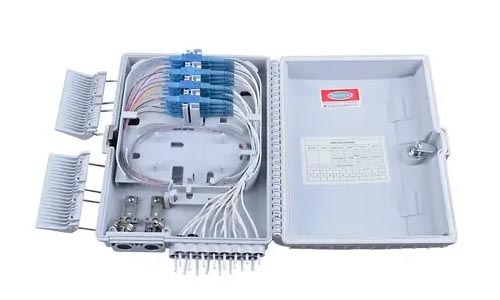 Fiber Optic Distribution Box
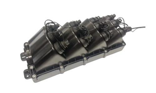 Multiport Service Termina Box
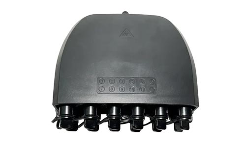 Fiber Optical Terminal Box
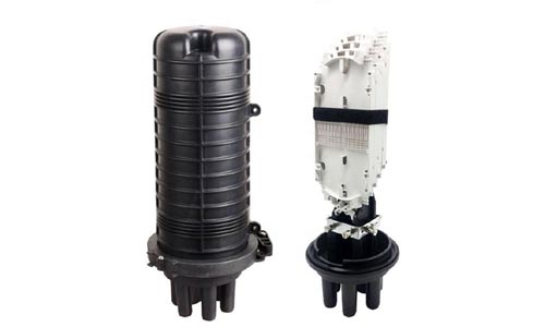 Fiber Optic Splice Closure
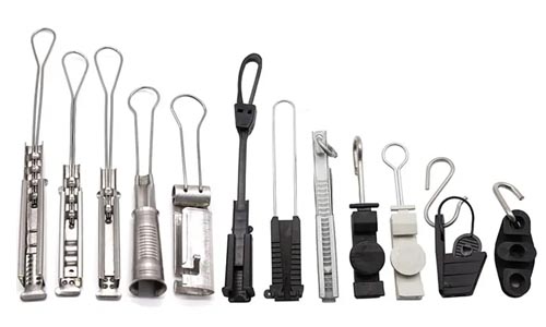 Fiber Optic Clamps
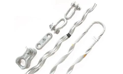 Fiber Optic Cable Fittings
 ADSS Fiber Cable
 ASU Fiber Cable
 OPGW Fiber Cable
 FTTH Fiber Cable
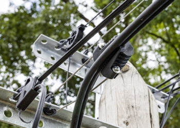 Figure 8 Fiber Cable
 Photoelectric Composite Fiber Cable
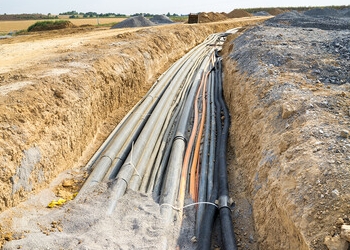 Underground & Pipeline Fiber Cable
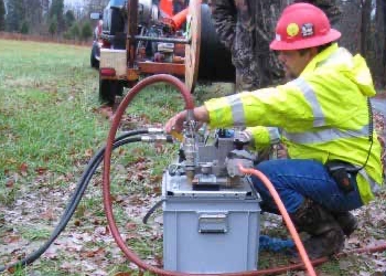 Air-Blown Micro Fiber Cable
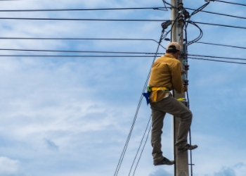 Aerial Fiber Cable
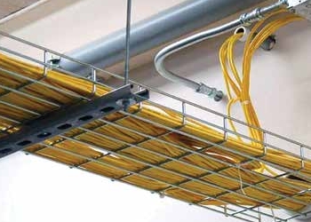 Indoor Fiber Cable
 Fiber Optical Terminal Box
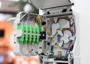 Fiber Optic Distribution Box
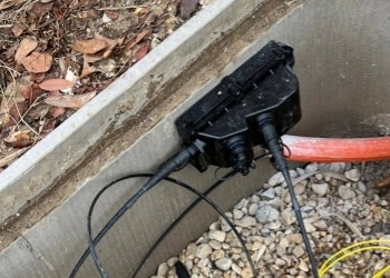 Multiport Service Termina Box
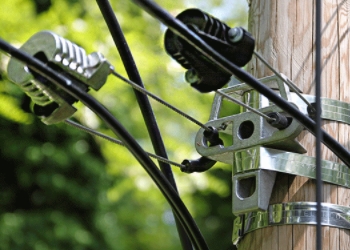 Fiber Optic Clamps
 About Us
 Our Team
 History
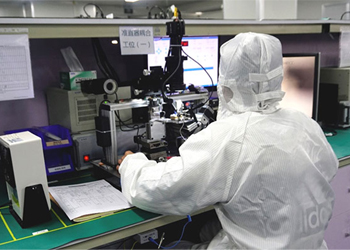 R&D Strength
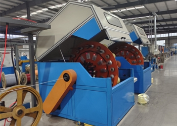 Production Base
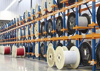 Warehouse & Logistics
 Quality
 FAQs
FAQs
G.657.A1 vs G.657.A2: Bend‑Insensitive Single‑Mode Fiber Complete Comparison
2026-08-06
FTTH, FTTB, MDU multi‑dwelling‑unit indoor wiring, compact data‑center cabling and micro‑duct deployment put forward strict requirements for fiber bending performance. Traditional G.652.D single‑mode fiber will produce obvious macrobending loss when the bending radius is too small, resulting in excessive optical attenuation, unstable PON service, intermittent drop‑out and even fiber fracture on site. ITU‑T released the G.657 standard to solve this pain point, defining two mainstream backward‑compatible bend‑insensitive fiber variants: G.657.A1 and G.657.A2.
Many network engineers, project contractors and procurement personnel face universal puzzles: What is the real technical gap between G.657.A1 and G.657.A2? Since they look identical visually, how to avoid being cheated by mis‑labeled products? Which scenario picks A1 and which must use A2? Many projects suffer hidden‑trouble risks: using A1 in narrow‑space heavy‑bending environment, leading to acceptance failure, repeated after‑sales maintenance and higher total‑project‑cost in the long run, even though the initial material cost is saved.
This article compares G.657.A1 and G.657.A2 from ITU‑T standard parameters, bending loss, compatibility, application scenarios, cost‑benefit analysis, typical engineering pitfalls and procurement verification methods, helping you make correct fiber selection for FTTH, indoor wiring, MDU and micro‑duct projects.

1. Core Definition & ITU‑T Standard Parameters
Both G.657.A1 and G.657.A2 belong to Category‑A bend‑insensitive single‑mode fiber, fully backward compatible with classic G.652.D fiber, which means matching mode‑field‑diameter, can be directly spliced or connected with existing G.652.D deployed network without extra‑high splicing loss. They are low‑water‑peak single‑mode fiber, supporting O/S/C/L multi‑band transmission, adapting to PON, 10G PON, XGS‑PON and future high‑speed optical access networks.
The most essential difference lies in minimum allowable bending radius and macrobending‑loss index under small‑radius bending, defined by ITU‑T G.657‑2024 standardITU.
| Parameter | G.657.A1 | G.657.A2 |
|---|---|---|
| Specified minimum bend radius | 10 mm | 7.5 mm |
| Macrobending loss @15 mm radius,10 turns,1550 nm | ≤0.25 dB | ≤0.03 dB |
| Macrobending loss @10 mm radius,1 turn,1550 nm | ≤0.75 dB | ≤0.10 dB |
| Macrobending loss @7.5 mm radius,1 turn,1550 nm | Not specified | ≤0.50 dB |
| Mode‑field diameter@1310 nm | 8.6±0.4 μm | 8.6±0.4 μm |
| Compatibility | Fully compliant with G.652.D | Fully compliant with G.652.D |
| Typical relative cost | Baseline | +8~15 % higher than A1 |
Critical note: There is no visual difference between bare fiber of G.657.A1 and G.657.A2. You cannot tell them apart by coating color or appearance. Only macrobending‑loss laboratory test can verify true model. Many bad suppliers label G.657.A1 as G.657.A2 to earn extra profit, which is a major hidden risk in procurement work.
2. In‑depth performance comparison
2.1 Bending resistance & macrobending loss
Macrobending loss is the core index distinguishing these two fibers. When fiber bends, part of light‑signal overflows cladding, generating attenuation. The smaller bending radius, the more obvious overflow effect.
G.657.A1 is optimized for 10 mm minimum bending radius. Under normal‑radius construction, its performance is stable. But when forced into 7.5 mm sharp bend, macrobending loss rises sharply, which will push PON link budget out‑of‑range, bring unstable ONU online, random packet loss, slow‑speed complaint from end‑users, especially obvious under 1550 nm and 1625 nm long‑wavelength signal.
G.657.A2 adopts advanced core‑cladding doping design, greatly suppresses light leakage under small‑radius bending. At 15 mm bending radius, ten‑turn macrobending loss is only ≤0.03 dB, far lower than A1. It stably supports 7.5 mm minimum bending radius. Even when installer makes sharp 90‑degree corner routing, compact coiling inside splice closure or narrow‑size optical‑box, signal attenuation keeps at low level, bringing higher construction tolerance for field‑workers. Even improper manual operation will not immediately trigger serious optical‑loss failure.
2.2 Network compatibility and splicing performance
Both A1 and A2 match G.652.D mode‑field‑diameter. Field‑technicians can directly splice G.657.A1/A2 with legacy G.652.D fiber in outside‑plant network. No special splicing‑program modification required. Normal calibrated fusion splicer can get qualified splicing loss value.
Practical construction tip: Although compatibility is good, dirty fiber end‑face, poor cutting quality will still cause high splicing loss. For mixed‑fiber‑type splicing, high‑precision cleaver and regularly‑calibrated fusion‑splicing equipment are strongly recommended to guarantee link‑quality.
2.3 Mechanical reliability
Both two fibers meet 0.69 GPa proof‑stress mechanical standard of ITU‑T. In terms of tensile resistance, coating‑layer mechanical property, there is no obvious gap. The difference is reflected in mechanical‑stress‑resisting performance under repeated sharp bending scenarios. G.657.A2 can bear more frequent small‑radius bending without hidden crack risk, suitable for scenarios where fiber may be repeatedly adjusted and rearranged after installation.
2.4 Cost and supply‑chain status
G.657.A1 has relatively simple manufacturing process, sufficient global supply, stable price, suitable for large‑volume mass‑project procurement.
G.657.A2 requires precise doping‑process control. Raw‑material cost is higher. In certain market cycles, supply may be tight, quotation validity period is short, price fluctuation is bigger. Many project managers tend to choose A2 for all‑scenario use, which brings unnecessary cost waste for projects without small‑bending requirement.
3. Application Scenario Analysis: When to pick G.657.A1, when to pick G.657.A2
Choose G.657.A1 for these scenarios
- Standard FTTH drop‑cable deployment: from street distribution cabinet to building external wall, routing path is relatively open, without frequent ultra‑sharp corners.
- New‑building MDU wiring: sufficient pipeline space, construction‑spec strictly controls bending radius ≥10 mm.
- Large‑scale civil‑engineering projects with tight‑budget, most routes are straight, only partial gentle‑bend sections.
- Mixed‑network reconstruction project, mass‑splicing with existing G.652.D outside‑plant fiber, pursuing cost‑performance balance.
G.657.A1 provides qualified bend‑insensitive capability at lower material cost. As long as construction team strictly follows 10 mm minimum‑bending‑radius specification, network‑running‑stability can be fully guaranteed.
Must select G.657.A2 for these scenarios
- Old‑building renovation indoor wiring: narrow concealed conduit, wall‑corner 90‑degree sharp turn, limited wiring space.
- High‑density MDU, compact optical‑distribution‑box, splice closure internal dense coiling, limited‑space cabinet wiring.
- Micro‑duct deployment, indoor pre‑terminated fiber jumper, building‑in‑wall buried fiber.
- Retrofitting project with uncontrollable on‑site construction quality: installer may produce excessive‑small‑radius bending during construction. Use A2 to improve fault‑tolerance of whole link.
- High‑reliability requirement customer network: enterprise‑building, high‑end community, avoid after‑sales maintenance caused by bending‑loss failure.
Important reminder: If you deploy G.657.A1 in scenarios requiring 7.5 mm bending performance, you may pass factory‑acceptance test, but hidden‑trouble will break out after months of operation: temperature change, slight fiber displacement will lead to gradual increase of macrobending loss, triggering service failure. This fault is hard to locate in daily‑operation‑maintenance work, bringing high OPEX cost for operators.
4. Universal industry pain points & typical mistakes
Pain point 1: Visual‑identification illusion
Many buyers mistakenly believe that they can distinguish A1/A2 through fiber appearance. In fact bare fiber coating, cable outer‑jacket appearance have no difference. Mis‑labeled cable is difficult to screen out when receiving goods, problems only emerge after construction completion, bringing huge rework‑cost for project side.
Pain point 2: Over‑spec or under‑spec selection
Two common wrong tendencies:
- All‑in‑A2: Regardless of actual‑deployment‑environment, all‑procure G.657.A2, causing unnecessary project‑cost increase.
- All‑in‑A1: Pursue low‑cost blindly, use A1 in old‑house‑renovation, narrow‑pipe‑line heavy‑bending scenario. Acceptance index is unqualified, or later‑period service instability occurs.
Correct logic: Differentiate according to actual‑on‑site‑routing condition. Divide project‑area: use A1 for open‑route part, adopt A2 for indoor‑narrow‑space‑wiring segment, realize balance of cost and performance.
Pain point 3: Confuse G.657.A series and G.657.B series
G.657.A1/A2 keeps full G.652.D backward‑compatibility, fit for FTTH access network. G.657.B2/B3 target ultra‑small‑bending‑radius indoor‑short‑distance wiring, partial‑index deviates from G.652.D, not suitable for long‑distance‑outside‑plant splicing scene. Many engineers mix‑up A‑series and B‑series, causing compatibility risk in network reconstruction projectITU.
Pain point 4: Ignore batch‑test report in procurement
Purchase‑order only marks fiber‑type, but does not require supplier to provide batch‑macrobending‑loss‑test report. Once counterfeit‑replacement happens, project‑party bears all loss.
5. Practical procurement & deployment best practices
- Clear technical‑clause in purchasing document: Distinguish fiber‑type according to sub‑scenario, not uniformly specify one‑model for whole project.
- Require supplier to provide batch‑corresponding macrobending‑loss test‑report, focus on 1550 nm macrobending‑loss index under 15 mm and 10 mm bending radius, this is the most effective means to identify true‑and‑false A1/A2.
- For construction specification: Even using G.657.A2, do not arbitrarily‑destruct‑bending‑radius in construction. Small‑bending‑resistance is fault‑tolerance‑capability, not encouraging‑bad‑construction‑behavior. Standard‑construction still shall be followed.
- Link‑budget calculation: When designing PON link, reserve certain attenuation‑margin for macrobending‑loss, especially for indoor wiring section.
- Acceptance‑test: Not only test overall‑link‑loss, but also pay attention to long‑wavelength‑(1550 nm,1625 nm) attenuation value. Long‑wavelength is more sensitive to macrobending loss, can expose hidden‑bending‑defect effectively.
6. Summary
G.657.A1 and G.657.A2 are both mature bend‑insensitive single‑mode‑fiber for modern FTTx network. G.657.A1 targets general‑FTTH‑drop‑cable and moderate‑bending‑scene, with obvious cost‑advantage; G.657.A2 is oriented to narrow‑space, old‑building‑renovation, high‑density‑indoor‑wiring scene, providing stronger anti‑macrobending‑performance and higher‑construction‑fault‑tolerance, at the cost of higher‑price.
There is no absolute better‑one between G.657.A1 and G.657.A2. The core of selection is matching fiber‑performance with real‑installation‑condition. Blind‑pursuit of high‑spec or excessive‑pursuit of low‑cost will both bring project‑risk. Engineers and procurement managers need to combine pipeline‑condition, renovation‑or‑new‑build, construction‑team‑ability, project‑budget to make rational decision. Meanwhile, strengthen incoming‑material‑verification, guard against mis‑labeled‑product risk, avoid heavy‑loss after‑cable‑laying‑completion.
For operators, system‑integrators and cable‑buyers, mastering the difference of G.657.A1 vs G.657.A2 helps optimize network‑stability, control total‑life‑cycle‑cost, reduce after‑sales‑maintenance workload of FTTH project.