 Optical Fiber
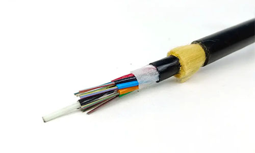 ADSS Fiber Optic Cable
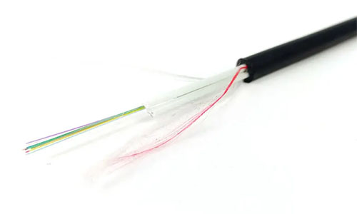 ASU Fiber Optic Cable
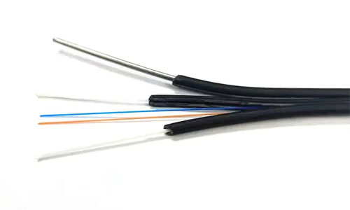 FTTH Fiber Optic Cable
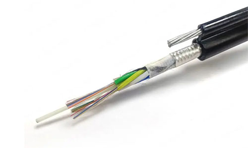 Figure 8 Fiber Optic Cable
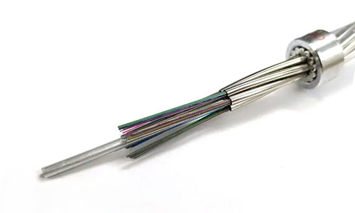 OPGW Fiber Optic Cable
 Coaxial Cable
 Ethernet Cable
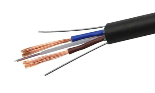 Photoelectric Composite Fiber Optic Cable
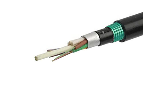 Underground & Pipeline Fiber Optic Cable
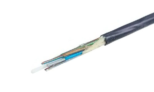 Air-Blown Micro Fiber Optic Cable
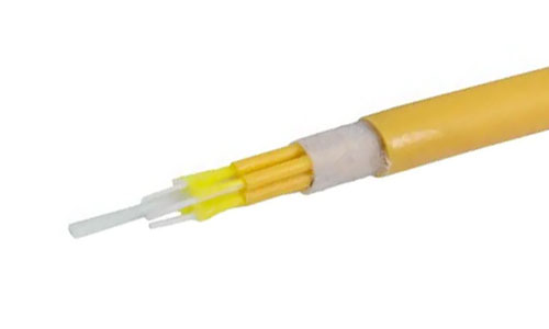 Indoor Fiber Optic Cable
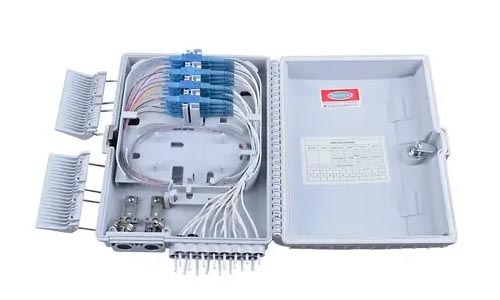 Fiber Optic Distribution Box
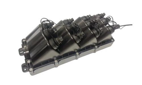 Multiport Service Termina Box
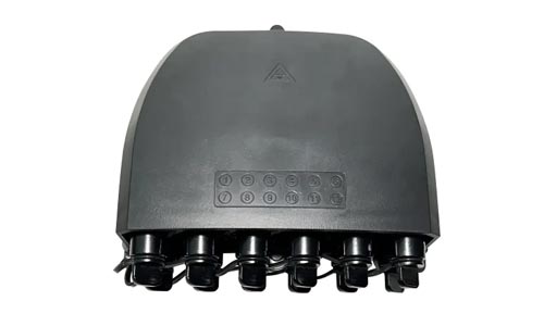 Fiber Optical Terminal Box
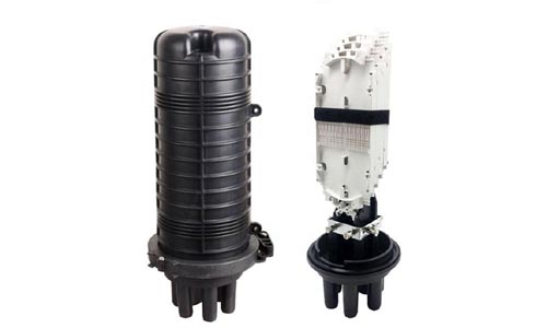 Fiber Optic Splice Closure
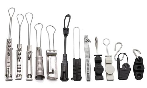 Fiber Optic Clamps
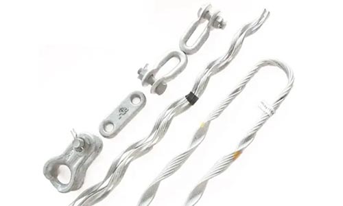 Fiber Optic Cable Fittings
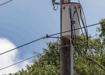 ADSS Fiber Cable
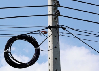 ASU Fiber Cable
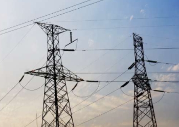 OPGW Fiber Cable
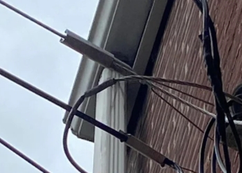 FTTH Fiber Cable
 Figure 8 Fiber Cable
 Photoelectric Composite Fiber Cable
 Underground & Pipeline Fiber Cable
 Air-Blown Micro Fiber Cable
 Aerial Fiber Cable
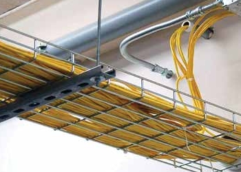 Indoor Fiber Cable
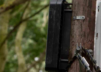 Fiber Optical Terminal Box
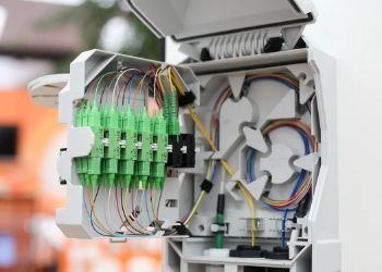 Fiber Optic Distribution Box
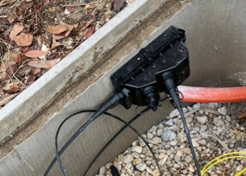 Multiport Service Termina Box
 Fiber Optic Clamps
 About Us
 Our Team
 History
 R&D Strength
 Production Base
 Warehouse & Logistics
 Quality
 FAQs
FAQsRodent Resistance of Different Types of Optical Fiber Cables
1. Introduction
In the transmission and processing of information, Optical Fiber Cables (OFCs) play a crucial role. They are considered the highways of telecommunications and telematics. Therefore, it is of the utmost importance that they guarantee safe connections at all times. Occasionally, however, the operational life time of an OFC could be threatened by rodents, for instance when OFCs are installed in ducts readily accessible to rats. In such environments the OFCs have to be protected, because rats have a natural propensity to gnaw and attack the OFCs when their exit is obstructed in these ducts.
For an optimum cable design, cable manufacturers prefer to use a material that combines reinforcing properties with rodent protection. They also want the OFCs to be flexible and light, and to have a small diameter. The materials to reinforce dielectric OFCs are predominantly aramid and E-glass to a lesser extent. The use of aramid is very popular and is rapidly increasing because of its unrivalled combination of mechanical and chemical properties and its good processing properties, resulting in very cost-effective OFCs with excellent performance and long-term reliability. However, the question whether E-glass and aramid ensure sufficient rodent protection has often been raised. It was difficult to get a clear answer from OFC end-users. The experiences of OFC end-users in Switzerland for example, showed that in some cases both E-glass and aramid-reinforced cables were so severely damaged by rats that they did not function properly anymore. To clarify the situation on rodent protection and to support the manufacturers of dielectric OFCs, we decided in cooperation with one of our Swiss customers to call in an independent research institute, TNO (a Dutch organization for applied scientific research), to carry out a study under practical conditions to test the rodent resistance of several types of OFCs.
2. Experimental
Test set-up
To test the rodent resistance of OFCs, TNO used Sprague Dawley rats housed in cages specially designed for this study. These cages were divided into two compartments by means of a partition provided with a circular hole to connect the two compartments (see Fig. 1). One of the compartments was illuminated and the other one was darkened. During the trials the entrance to the darkened compartment, in which the food of the rats was located, was blocked by the OFCs on test. Since rodents prefer a dark environment, they will spend the greater part of their time on the dark side. So, there were two stimuli for the rats to get into the darkened compartment. During the whole test period the rats had free access to water. After the rats were accustomed to the conditions in the cages, the first trials were started.
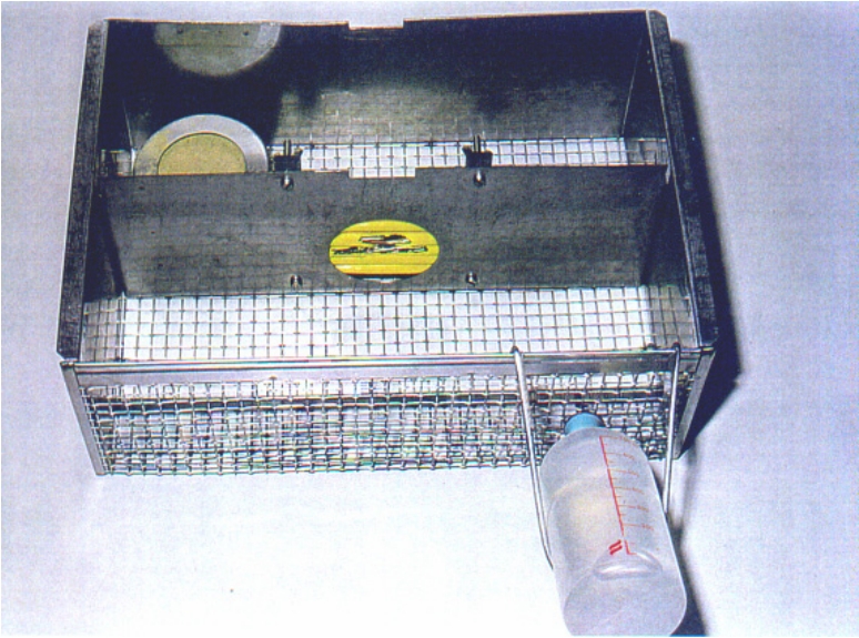
Fig. 1: Test cage divided into two compartments.
At the start of the trials, three rats were housed in the illuminated compartments of each cage for twosubsequent days, while the hole in the partition was blocked by the OFC design on trial (see Fig. 2).After this period the rats were transferred to other cages for four days and subsequently returned tothe test cages for two more days.
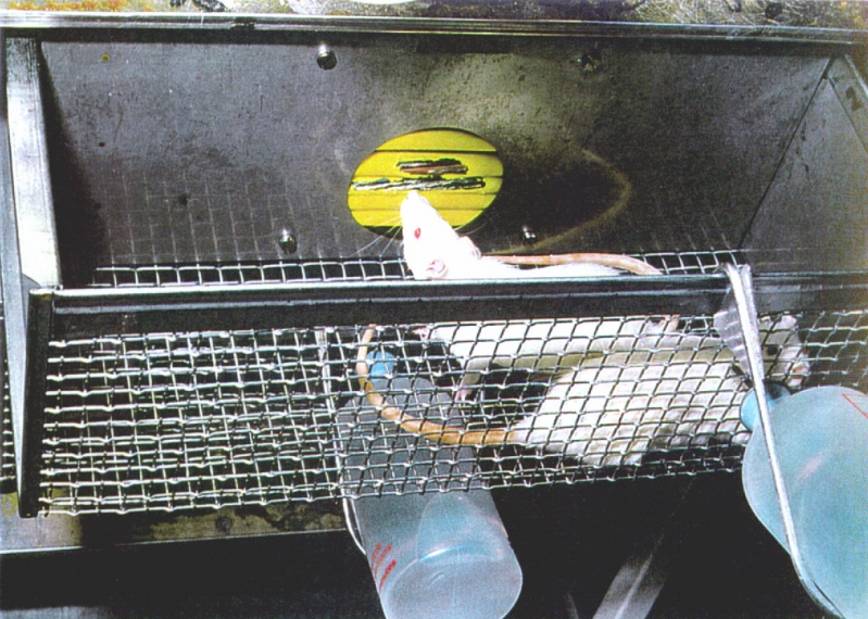
Fig. 2: Hole in the partition blocked by OFCs on trial.
OFC designs evaluated
Nine different OFC designs were evaluated for rodent resistance. These designs are all part of the group of designs that account for the largest part of the OFC-market. The OFCs can be divided into two categories:
1. Standard OFC designs using aramid yarn or E-glass (with or without impregnation) as reinforcing material beneath the PE outer sheath (Figs. 3a to 3d).
2. Special OFC designs to resist rodent attacks, e.g. double-layered constructions or constructions with PA12 or corrugated steel (Figs. 3e to 3i).
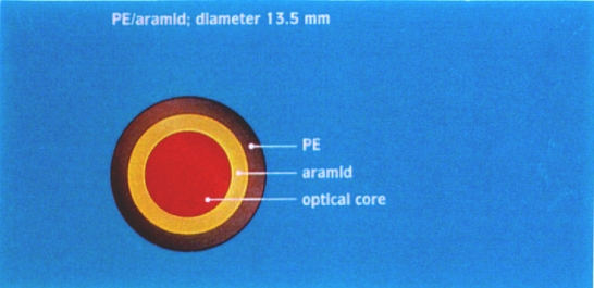
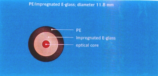
Fig. 3a: Cross section of a standard OFC design. Fig. 3b: Cross section of a standard OFC design.
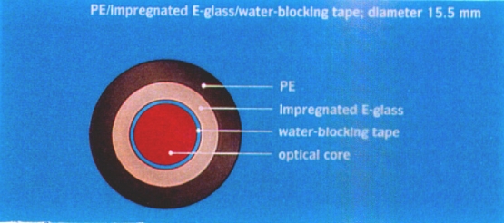
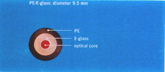
Fig. 3c: Cross section of a standard OFC design.Fig. 3d: Cross section of a standard OFC design.
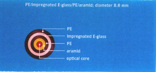
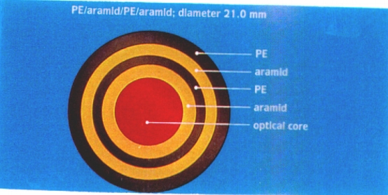
Fig. 3e: Cross section of a special OFC design.Fig. 3f: Cross section of a special OFC design.
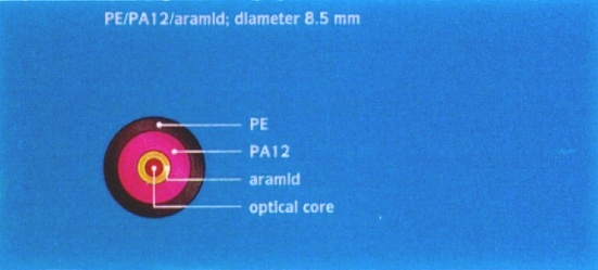
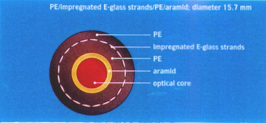
Fig. 3g: Cross section of a special OFC design.Fig. 3h: Cross section of a special OFC design.
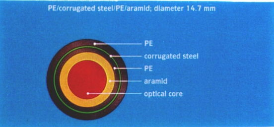
Fig. 3i: Cross section of a special OFC design.
3. Results and discussion
After the two test periods of two days each, the damage due to rodent attacks was examined. In Figs. 4a to 4i you will see two pictures of each of the tested cable designs; the upper picture showing the least damaged and the lower one showing the most damaged OFC. The results of the macroscopic examination of the cables clearly show differences in damage between the nine OFC designs. But, as you can see in the pictures, all OFCs - with the exception of the corrugated steel/aramid design - are damaged in such a way that one might expect long-term transmission properties to be affected. This also holds for the OFC designs PE/impregnated E-glass/water-blocking tape (Fig. 4d) and PE/impregnated E-glass strands/PE/aramid (Fig. 4h), although these designs show less severe damage. In practice, however, one deals with nondomestic rodents, which could involve more aggressive and persistent attacks in case of entrapment of the rodent. Therefore, on the basis of the TNO test results, the conclusion must be that of the tested designs only the corrugated steel/aramid design is fully rodent resistant.
The rodent resistance of an OFC can also be improved by the use of outer sheaths made of amorphous polyamide or polyamide copolymers with a very high Shore D hardness. Therefore, we suggest cable designers to improve the rodent resistance of OFCs by using corrugated steel (e.g. Zetabon) or sheaths made of amorphous polyamide or polyamide copolymers (e.g. Grilamid). The use of corrugated steel seems to be the optimum choice.
The suggestion that the cable diameter affects the rodent resistance of an OFC - to the effect that from a certain cable diameter onward a positive influence on rodent resistance might occur - is interesting and further study could prove worthwhile for cable designers.
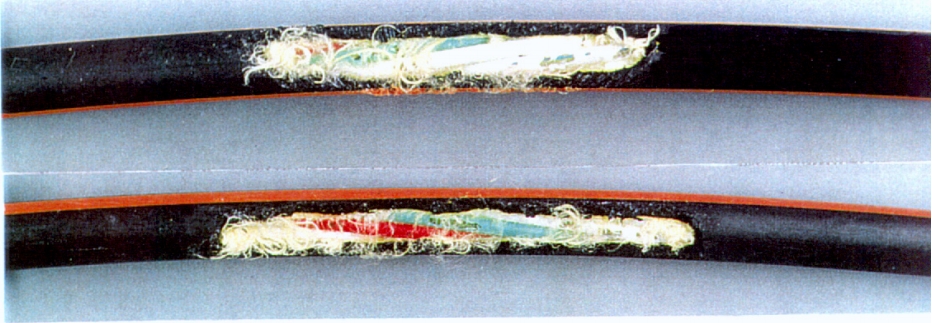
Fig. 4a: PE/aramid cable design after trial; diameter 13.5 mm.
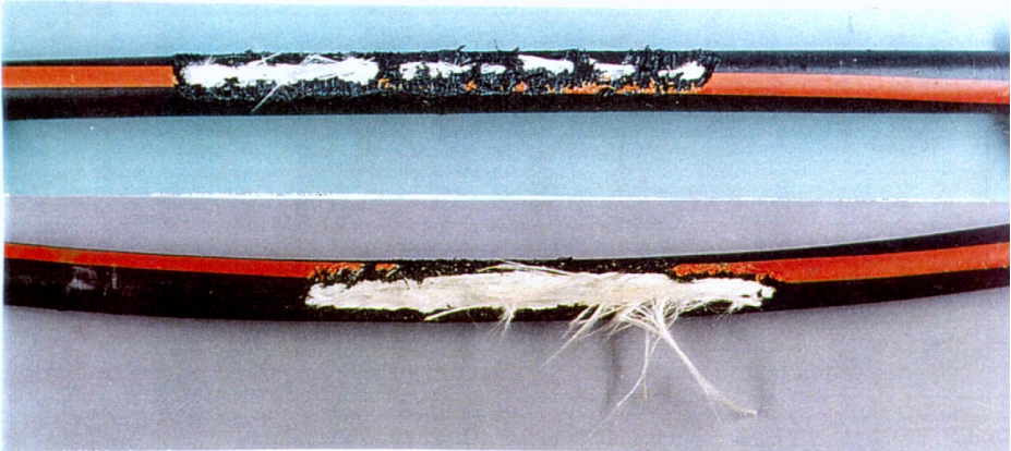
Fig. 4b: PE/impregnated E-glass cable design after trial; diameter 11.8 mm.
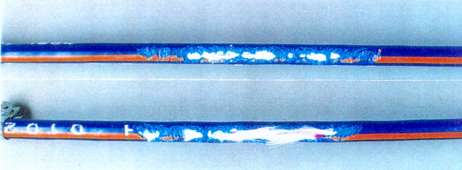
Fig. 4c: PE/E-glass cable design after trial; diameter 9.5 mm.
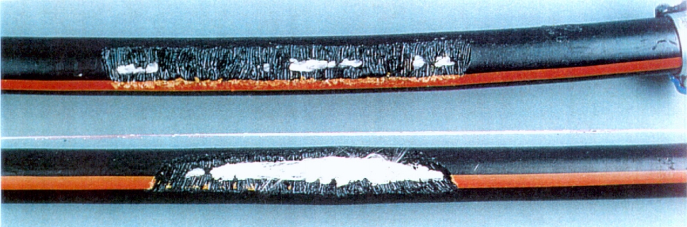
Fig. 4d: PE/impregnated E-glass/water-blocking tape cable design after trial; diameter 15.5 mm.
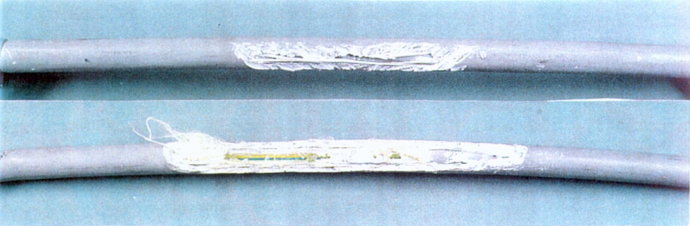
Fig. 4e: PE/impregnated E-glass/PE/aramid cable design after trial; diameter 8.8 mm.
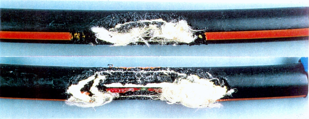
Fig. 4f: PE/aramid/PE/aramid cable design after trial; diameter 21 mm.
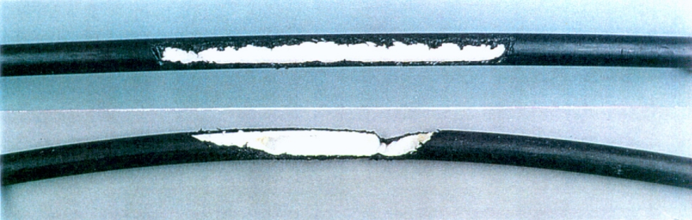
Fig. 4g: PE/PA12/aramid cable design after trial; diameter 8.5 mm.
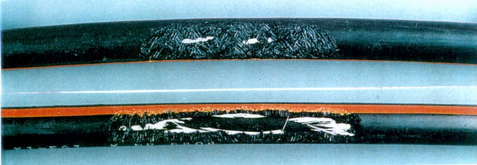
Fig. 4h: PE/impregnated E-glass strands/PE/aramid cable design after trial; diameter 15.7 mm
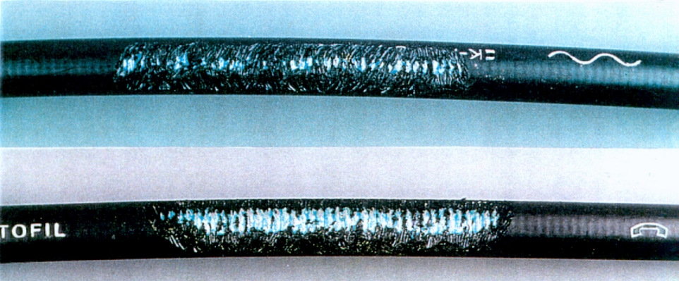
Fig. 4i: PE/corrugated steel/PE/aramid cable design after trial; diameter 14.7 mm.
4. Conclusion
On the basis of the results of the trials, TNO has concluded that of the tested OFC designs only the corrugated steel/aramid design is fully rodent resistant. All other designs (reinforced with E-glass with or without impregnation- or aramid, or with a sheath of PA12) did not sufficiently resist rodent attacks. The study clearly demonstrates that if rodent resistance is required one must pay special attention to cable design.